 | |
No good robot can ever be built without gears. As such, a good understanding of how gears affect parameters such as torque and velocity are very important. In this tutorial I will first talk about the basics of gears, how to use them properly along with simple equations, and then I will go into specific types of gears.
Mechanical Advantage, Torque vs. Rotational Velocity
Gears work on the principle of mechanical advantage. This means that by using different gear diameters, you can exchange between rotational (or translation) velocity and torque.
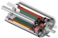 As with all motors, by looking at the motor datasheet you can determine the output velocity and torque of your motor. But unfortunately for robots, motors commercially available do not normally have a desirable speed to torque ratio (the main exception being servos and high torque motors with built in gearboxes). For example, do you really want your robot wheels to rotate at 10,000 rpm at low torques? In robotics, torque is better than speed.
 With gears, you will exchange the high velocity with a better torque. This exchange happens with a very simple equation that you can calculate:
Torque_Old * Velocity_Old = Torque_New * Velocity_New
Torque_Old and Velocity_Old can be found simply by looking up the datasheet of your motor. Then what you need to do is put a desired torque or velocity on the right hand side of the equation. My statics and dynamics tutorials can help you decide on a reasonable torque and/or velocity for your robot.
So for example, suppose your motor outputs 3 lb-in torque at 2000rps according to the datasheet, but you only want 300rps. This is what your equation will look like:
3 lb-in * 2000rps = Torque_New * 300rps
With highschool algebra you can then determine that your new torque will be 20 lb-in.
Now suppose, with the same motor, you need 5 lb-in (minimum force to crush a cat, obviously). But suppose you also need 1500rps minimum velocity. How would you know if the motor is up to spec and can do this? Easy . . .
3 lb-in * 2000rps = 5 lb-in * Velocity_New
Velocity_New = 1200rps
You now have just determined that at 1200 rps the selected motor is not up to spec. Using the simple equation, you have just saved yourself tons of money on a motor that would have never worked. Designing your robot, and doing all the necessary equations beforehand, will always save you tons of money and time.
Gearing Ratios
I have done the equations, but how do you mechanically swap torque and velocity? You would use two gears (sometimes more) of different diameters to have a particular gearing ratio. In any pair of gears, the larger gear will move more slowly than the smaller gear, but it will move with more torque. Thus, the bigger the size difference (or gearing ratio) between two gears, the greater the difference in speed and torque.
The gearing ratio is the value at which you change your velocity and torque. Again, it has a very simple equation. The gearing ratio is just a fraction which you multiple your velocity and torque by.
Suppose your gearing ratio is 3/1. This would mean you would multiple your torque by 3 and your velocity by the inverse, or 1/3.
example; Torque_Old = 10 lb-in, Velocity_Old = 100rps
Gearing ratio = 2/3
Torque * 2/3 = 6.7 lb-in
Velocity * 3/2 = 150rps

Achieving a Particular Gearing Ratio
If you wanted a simple gearing ratio of say 2 to 1, you would use two gears, one being twice as big as the other. It isn't really the size as much as the diameter ratio of the two gears. If the diameter of one gear is 3 times bigger than the other gear, you would get a 3/1 (or 1/3) gearing ratio. You can easily figure out the ratio by hand measuring the diameter of the gears you are using. For a much more accurate way to calculate the gearing ratio, calculate the ratio of teeth on the gears. If one gear has 28 teeth and the other has 13, you would have a (28/13=2.15 or 13/28=.46) 2.15 or .46 gearing ratio. I will go into this later, but this is why worm gears have such high gearing ratios. In a worm gear setup, one gear always has a single tooth, while the other has many - a guaranteed huge ratio. Counting teeth will always give you the most exact ratio.
Gear Efficiency
Unfortunately, by using gears, you lower your input to output power efficiency. This is due to obvious things such as friction, misalignment of pressure angles, lubrication, gear backlash (spacing between meshed gear teeth between two gears) and angular momentum, etc. Different gear setups, different types of gears, different gear materials, and wear and tear on the gear, will all have different efficiencies. The possible combinations are too big to list, so I will give you an estimated efficiency to expect with each gear type below. You can also find a much more exact efficiency by looking up the datasheet on the gears you are using.
For example, suppose you use two spur gears, you would typically expect efficiency to be around ~90%. To calculate, multiply that number by your Velocity_New and Torque_New to get your true output velocity and torque.
if (from above example)
Gearing ratio = 2/3
Torque * 2/3 = 6.7 lb-in
Velocity * 3/2 = 150rps
then
true torque = 6.7 * .9 = 6 lb-in
true velocity = 150 * .9 = 135rps

Direction of Gear Rotation
When designing your gear setup you should understand how gearing changes the rotation direction of your output. Two gears touching will always be counter rotation, meaning if one rotates clockwise, the other will always rotate counterclockwise. Obvious, I know. But what if you have a chain of say 6 gears touching? The rule is, an odd numbers of gears always rotates in the same direction, and even numbers of gears are counter-rotational.

Gear Chains (more than 2 gears together)
Suppose you have 30 gears (holy squirrels!), all in order, like in the image above. How in the monkies do you calculate the gearing ratio of that behemoth? Easy. Ignore all the gears in between the very first and very last gear. If the diameter of the first gear is 2 inches, and the diameter of the last is 1 inch, you have a 2:1 ratio. The gears in between do not matter. Now what direction does the last gear rotate? Easy, you have an even number of gears, so it is counter-rotational of the first gear. What efficiency do you have? Well thats:
effienciency_total = gear_type_efficiency ^ (# of gears - 1) = .9 ^ (29) = 4.7 %
If instead you used 5 gears, you would have:
effienciency_total = .9 ^ (4) = 65.6 %
Compound Gears
A compound gear is where you have two gears fixed on the same shaft.
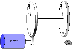 It is easy to figure out that if they are on the same shaft, the velocity (rotations per second) is the exact same. To calculate torque, you must use the moment arm balance equations from my statics tutorial. In this case, the radius is the moment arm.
 radius_gear1 * torque_gear1 = radius_gear2 * torque_gear2
In this example, what minimum torque does the motor need to pull the weight up?
writing down the equations:
torque_motor * radius_gear1 = torque_gear2 * radius_gear2
torque_gear2 * radius_gear2 = torque_gear3 * radius_gear3
torque_gear3 * radius_gear3 = weight * radius_gear3
simplifying, we get:
torque_motor * radius_gear1 = weight * radius_gear3
so therefore the minimum required motor torque is
torque_motor = weight * radius_gear3 / radius_gear1
Now what if you wanted the weight to lift at 2 feet/sec. What rotations per second and direction must the motor rotate at?
writing down the equations:
rps_motor * radius_gear1 = rps_gear2 * radius_gear2
rps_gear2 = rps_gear3
rps_gear3 * 2*pi*radius_gear3 = velocity_weight
simplifying, we get:
rps_motor * radius_gear1 = rps_gear3 * radius_gear2
or
rps_motor * radius_gear1 = velocity_weight / (2*pi*radius_gear3) * radius_gear2
so therefore the required motor rps is
rps_motor = 2 ft/sec * radius_gear2 / (2*pi*radius_gear3 * radius_gear1)
Gear Pitch
When selecting your gears, the three most important numbers you must know are pitch, pitch diameter, and number of teeth.
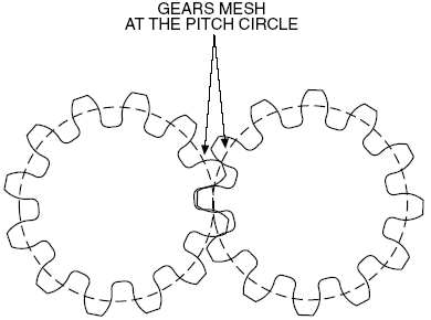
The pitch diameter is as shown. To calculate the pitch, simply use this equation:
Pitch = # teeth / pitch circle diameter (in inches)
For example, a gear with 72 teeth and a 1.5" pitch diameter is 48 Pitch. Gears that mesh must both have the same pitch and pressure angle (usually 20 degrees).
Gear Types
All gears, no matter the type, work on the same principles above. However the different types let you accomplish different things. Some types of gears have high efficiencies, or high gearing ratios, or work at different angles, for example. Below are the main common types. This is not a complete list. It is also possible to have a combination in types.
Note: The efficiencies listed are only typical. Because of many other factors could be present, the listed efficiencies should only be used as a guide. Often manufacturers will give you expected efficiencies in the datasheets for their gears. Remember, wear and lubrication will also dramatically affect gear efficiencies.
Spur Gears (~90% efficiency)
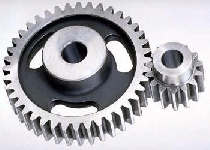
Spur gears are the most commonly used gears due to their simplicity and the fact that they have the highest possible efficiency of all gear types. Not recommend for very high loads as gear teeth can break more easily.
Helical Gears (~80% efficiency)
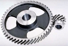
Helical gears operate just like spur gears, but offer smoother operation. You can also optionally operate them at an angle, too. Unfortunately, due to the complex shape, they are generally more expensive.
Sproket Gears With Chains (~80% efficiency)
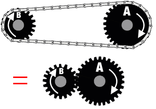
Two gears with a chain can be considered as three separate gears. Since there is an odd number, the rotation direction is the same. They operate basically like spur gears, but due to increased contact area there is increased friction (hence lower efficiency). Lubrication is highly recommended.
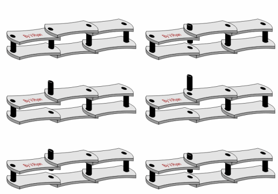
To change the length of any chain, you will need what is called a chain breaker. This is a cheap device you can buy at any bike store. It helps in removing and placing pins within the chain.
Bevel Gears (~70% efficiency)
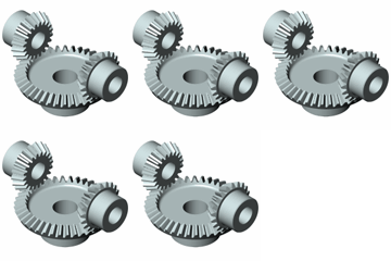
Bevel gears are good for changing the rotation angle. Unfortunately they suffer low efficiencies, so avoid use if possible.
Rack and Pinion (~90% efficiency)
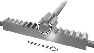
Rack and Pinion is the type of gearing found in steering systems. This gearing is great if you want to convert rotational motion into translational. Mathematically, use radius = 1 for the straight 'gear'.
Worm Gears (~70% efficiency)
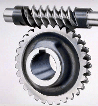
Worm gears have a very high gearing ratio. To mathematically calculate, consider the worm gear as a single tooth. Another advantage to the worm gear is that it is not back-drivable. What this means is only your motor can rotate the main gear, so things like gravity or counter forces will not cause any rotation. This is good say if you have a robot arm holding something heavy, and you don't want to waste power on holding torque. The efficiency is low, but lubrication really helps.
Planetary Gears (~80% efficiency)
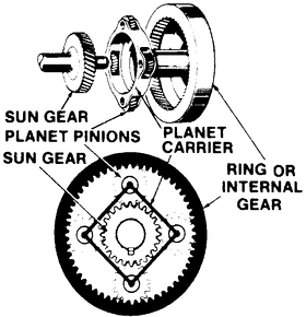
Planetary gears have the highest commercially available gear ratios you would ever want to put on a robot. But since they are somewhat complicated, you would never need to build one, just use it. The datasheet should tell you the gearing ratio - I just wanted you to know if you need a really really high gearing ratio for a robot, planetary gears are the way to go. Even better, some planetary gears offer multiple gearing ratio's that are user configurable!
