
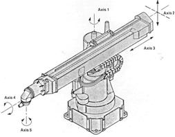
The degrees of freedom, or DOF, is a very important term to understand. Each degree of freedom is a joint on the arm, a place where it can bend or rotate or translate. You can typically identify the number of degrees of freedom by the number of actuators on the robot arm. Now this is very important - when building a robot arm you want as few degrees of freedom allowed for your application!!! Why? Because each degree requires a motor, often an encoder, and exponentially complicated algorithms and cost.
Denavit-Hartenberg (DH) Convention
The Robot Arm Free Body Diagram (FBD)
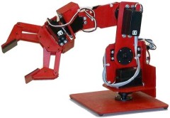
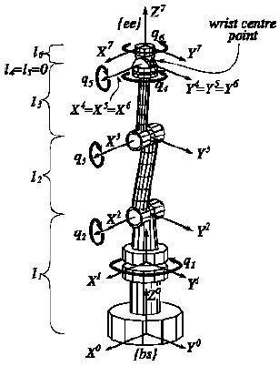
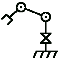
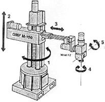
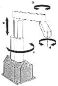
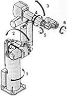
The Denavit-Hartenberg (DH) Convention is the accepted method of drawing robot arms in FBD's. There are only two motions a joint could make: translate and rotate. There are only three axes this could happen on: x, y, and z (out of plane). Below I will show a few robot arms, and then draw a FBD next to it, to demonstrate the DOF relationships and symbols. Note that I did not count the DOF on the gripper (otherwise known as the end effector). The gripper is often complex with multiple DOF, so for simplicity it is treated as separate in basic robot arm design.
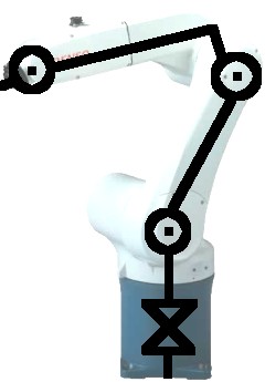
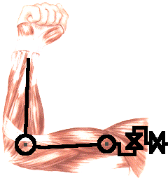
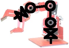 Notice between each DOF there is a linkage of some particular length. Sometimes a joint can have multiple DOF in the same location. An example would be the human shoulder. The shoulder actually has three coincident DOF. If you were to mathematically represent this, you would just say link length = 0.
Also note that a DOF has its limitations, known as the configuration space. Not all joints can swivel 360 degrees! A joint has some max angle restriction. For example, no human joint can rotate more than about 200 degrees. Limitations could be from wire wrapping, actuator capabilities, servo max angle, etc. It is a good idea to label each link length and joint max angle on the FBD.
 (image credit: Roble.info)
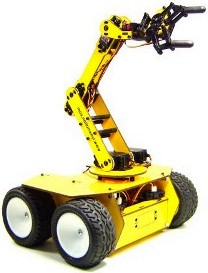
 Your robot arm can also be on a mobile base, adding additional DOF. If the wheeled robot can rotate, that is a rotation joint, if it can move forward, then that is a translational joint. This mobile manipulator robot is an example of a 1 DOF arm on a 2 DOF robot (3 DOF total).
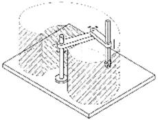
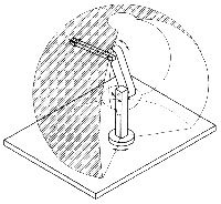
Robot Workspace
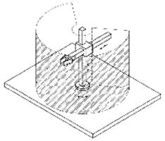
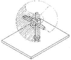
The robot workspace (sometimes known as reachable space) is all places that the end effector (gripper) can reach. The workspace is dependent on the DOF angle/translation limitations, the arm link lengths, the angle at which something must be picked up at, etc. The workspace is highly dependent on the robot configuration.
Since there are many possible configurations for your robot arm, from now on we will only talk about the one shown below. I chose this 3 DOF configuration because it is simple, yet isnt limiting in ability.
Now lets assume that all joints rotate a maximum of 180 degrees, because most servo motors cannot exceed that amount. To determine the workspace, trace all locations that the end effector can reach as in the image below.
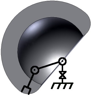
Now rotating that by the base joint another 180 degrees to get 3D, we have this workspace image. Remember that because it uses servos, all joints are limited to a max of 180 degrees. This creates a workspace of a shelled semi-sphere (its a shape because I said so).

If you change the link lengths you can get very different sizes of workspaces, but this would be the general shape. Any location outside of this space is a location the arm cant reach. If there are objects in the way of the arm, the workspace can get even more complicated.
Here are a few more robot workspace examples:
Cartesian Gantry Robot Arm
Cylindrical Robot Arm
Spherical Robot Arm
Scara Robot Arm
Articulated Robot Arm
Mobile Manipulators
A moving robot with a robot arm is a sub-class of robotic arms. They work just like other robotic arms, but the DOF of the vehicle is added to the DOF of the arm. If say you have a differential drive robot (2 DOF) with a robot arm (5 DOF) attached (see yellow robot below), that would give the robot arm a total sum of 7 DOF. What do you think the workspace on this type of robot would be?
Force Calculations of Joints
This is where this tutorial starts getting heavy with math. Before even continuing, I strongly recommend you read the mechanical engineering tutorials for statics and dynamics. This will give you a fundamental understanding of moment arm calculations.
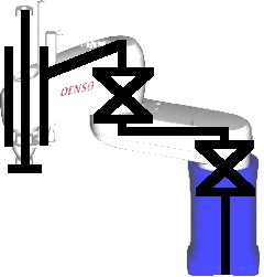
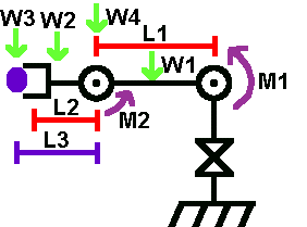
The point of doing force calculations is for motor selection. You must make sure that the motor you choose can not only support the weight of the robot arm, but also what the robot arm will carry (the blue ball in the image below).
The first step is to label your FBD, with the robot arm stretched out to its maximum length.
 | Choose these parameters:
|
Torque About Joint 1:
- M1 = L1/2 * W1 + L1 * W4 + (L1 + L2/2) * W2 + (L1 + L3) * W3
- M2 = L2/2 * W2 + L3 * W3
TUTORIAL FOR ROBOTS
 |
But actually electronics can be much simpler than you think. Learning electronics is more like learning a foreign language alphabet. At first glance it is all a bunch of squiggles. But actually each letter has its own pronounciation and its own rules of use. And certain combinations of letters in a certain order form a word of some meaning. And a combination of words forms a sentence. This is the same for a circuit board. Each tiny component, such as a resistor or capacitor or transistor, has special rules and abilities. Combining a few into a circuit can create interesting effects. Combine a bunch of unrelated circuits together and suddenly you have a robot. So your first step would just to be to learn and understand the smallest of the components. Once there you can learn about combining them. Just like learning a foreign alphabet, no?
Ok first a quick crash course in electron physics.
All electronics is designed to manipulate a flow of electrons. Electrons have mass and volume so you can almost think of electrons in circuits as water flowing through plumbing. The analogy is amazingly helpful if you think about it. Also note, the more electrons you have in one place, the higher the voltage. The more electrons moving together, the higher the current. The same as with water.
POWER
Power is simply the energy required to do something. If you are moving a large amount of electrons, and moving them through something that is resistant of that movement, power is used. Power is voltage times current. Power is also voltage squared divided by resistance.
P = I * V
P = (V^2)/R
Ground and Source

Source is the positive part of your circuit. The plus end of your battery would go here. Ground is the negative node of your circuit. When you design your circuit, imagine a flow of electrons coming from the source, and heading to the ground. A quick note, in reality electrons move from gound to source. The confusion has historical reasons I dont want to get in to. But just know this fact, and pretend electrons move from source to ground.
Now think of this as water.
Water flows down the easiest quickest path between these two points. More resistance to flow, less will flow.
RESISTORS

These do exactly what they say. They resist the flow of electrons. These are necessary for several reasons:
- they can control how much current goes down each wire
- they can control power usage
- they can control voltages (since current, resistance, and voltage are interrelated)
The last point is important as it is the basis of Ohm's law, V=IR. Voltage = Current x Resistance. For example, suppose you take a resistor and connect the two ends of a battery with it. You know that your battery is 9V (or whatever) and you know the resistor is 3Kohm (determined by the color stripes on the resistor), so 9V divided by 3Kohm is .003amps (3 milliamps). So why is this information useful? Well now that you know the current, you can determine other useful things such as power. P=IV. You will notice that if you increase resistance, you decrease current. If you decrease current, you decrease power use. Put a 1ohm resistor between the battery and it will get so hot it could burn because of the power use. Use a 100Kohm resistor and almost no power at all will be used.
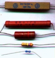
So about determining the value of a resistor, all resistors have the value labled on them. You will notice colored stripes on the resistor. Each stripe means a certain number. This has been explained a billion times online already so I won't, just google search 'resistor color tutorial.'
Click for a quick resistor color code reference chart.

CAPACITORS

Now suppose you want to control how the current in your circuit changes (or not changes) over time. Now why would you? Well radio signals require very fast current changes. Robot motors cause current fluctuations in your circuit which you need to control. What do you do when batteries cannot supply current as fast as you circuit drains them? How do you prevent sudden current spikes that could fry your robot circuitry? The solution to this is capacitors.
Capacitors are somewhat complex in theory, but most people can get by on the basics which I will explain here. Capacitors are like electron storage banks. If your circuit is running low, it will deliver electrons to your circuit. If your circuit is in excess (such as when your robot motors are turned off), it will store electrons. In our water analogy, think of this as a water tank with water always flowing in, but with drainage valves opening and closing. Since capacitors take time to charge, and time to discharge, they can also be used for timing circuits. Timing circuits can be used to generate signals such as PWM or be used to turn on/off motors in solar powered BEAM robots.
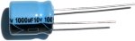
Quick note, some capacitors are polarized, meaning current can only flow one direction through them. If a capacitor has a lead that is longer than the other, assume the longer lead must always connect to positive.
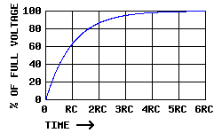
How do capicitors charge over time? This Capacitor Charge Curve Chart should help. The discharge rate would be the direct inverse. Theoretically (as made obvious by the graph) a capacitor can never be fully charged or discharged, but in reality this is never the case.
So how can you use capacitors in your robot?
Power surge/drainage management.
The problem with using robot components that drain a large amount of power is sometimes your battery cannot handle the high drain rate. Motors and servos being perfect examples. This would cause a system wide voltage drop, often reseting your microcontroller, or at least causing it to not work properly. Just a side note, it is bad to use the same power source for both your control circuitry and your motors. So don't do it.
Or suppose your robot motors are not operating at it's full potential because the battery cannot supply enough current, the capacitor will make up for it. The solution is to place a large electrolytic capacitor between the source and ground of your power source. Get a capacitor that is rated at least twice the voltage you expect to go through it. Have it rated at 1uF-10uF for every amp required. For example, if your 20V motors will use 3 amps, use a 3uF-30uF 50V rated capacitor. Exactly how much will depend on how often you expect your motor to change speed and direction, as well as momentum of what you are actuating. Just note that if your capacitor is too large, it make take a long time to charge up when you first turn your robot on. If it is too small, it will drain of electrons and your circuit will be left with a deficit. It is also bad to allow a large capacitor to remain fully charged when you turn off your robot. Things could accidently short and fry, such as curious kitties that get too close. So use a simple power on LED in your motor circuit to drain the capacitor after your robot is turned off. If your capacitor is not rated properly for voltage, then can explode with smoke. Fortunately they do not overheat if given excessive amounts of current. So just make sure your capacitor is rated higher than your highest expected.
Capacitors can also be used to prevent power spikes that could potentially fry circuitry. Next to any on/off switch or anything that that could affect power suddenly should have a capacitor across it.
Capacitors can eliminate switch bouncing. When you flip a mechanical switch, the switch actually bounces several times within a microsecond range. Normally this is too small of a time for anyone to care (or even notice), but note that a microcontroller can take hundreds of readings in a single microsecond. So if your robot was counting the number of times a switch is flipped, a single flip can count as dozens. So how do you stop this? Use a small ceramic capacitor! Just experiment until you find the power capacitance value.
Capacitors can improve efficiency and longevity of electric motors up to 100%. Place a small ceramic capacitor of like 10uF across the two leads of your motor. This works really well with el-cheap-o motors. Not much effect with high-end expensive motors however. These capacitors will also signficantly reduce EMI (Electro Magnetic Interference) and system noise too.
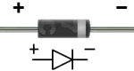
DIODES
Diodes are what you would use to ensure current flows in only a single direction. A great water analogy to a diode is a dam. Water never flows up a damn. But the analogy goes even further. With diodes, there is always a voltage across it (typically .7V forward voltage). Meaning if you have a diode come after a 7.2V battery, the voltage would then be 6.5V. This is just like a dam in that the water level will always drop. Doesnt current already always flow in only a single direction? No. RC circuits, or circuits involving AC power, or circuits that are noisy (such as with motors), involve currents that changes directions. So why would you only want current to flow in a single direction? Many many reasons. But for a beginner, you need to protect your circuitry from noise. A microcontroller would fry if current went the wrong way. Motor drivers and MOSFETs would too. Diodes are also useful for dropping high voltages to a lower more usable voltage.
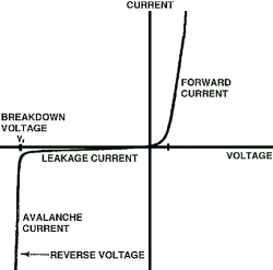
This below chart represents the current vs voltage curve typical of diodes. As you can see, the current passing through a diode changes non-linearly as voltage changes linearly.
There is another special diode called a zener diode. With the water analogy, a zener diode is like a dam, but with a pump at the bottom pumping water back to the top. Zener diodes allow current to flow in reverse as well as forward. The forward voltage is still around .7V, but there is a different reverse voltage of around negative ~2.3V. You will probably never need to use a zener diode.
If you would like to learn more about the LED, check out my LED tutorial.
 |
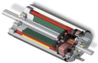
No good robot can ever be built without gears. As such, a good understanding of how gears affect parameters such as torque and velocity are very important. In this tutorial I will first talk about the basics of gears, how to use them properly along with simple equations, and then I will go into specific types of gears.
Mechanical Advantage, Torque vs. Rotational Velocity
Gears work on the principle of mechanical advantage. This means that by using different gear diameters, you can exchange between rotational (or translation) velocity and torque.
As with all motors, by looking at the motor datasheet you can determine the output velocity and torque of your motor. But unfortunately for robots, motors commercially available do not normally have a desirable speed to torque ratio (the main exception being servos and high torque motors with built in gearboxes). For example, do you really want your robot wheels to rotate at 10,000 rpm at low torques? In robotics, torque is better than speed.
With gears, you will exchange the high velocity with a better torque. This exchange happens with a very simple equation that you can calculate:
Torque_Old * Velocity_Old = Torque_New * Velocity_New
Torque_Old and Velocity_Old can be found simply by looking up the datasheet of your motor. Then what you need to do is put a desired torque or velocity on the right hand side of the equation. My statics and dynamics tutorials can help you decide on a reasonable torque and/or velocity for your robot.
So for example, suppose your motor outputs 3 lb-in torque at 2000rps according to the datasheet, but you only want 300rps. This is what your equation will look like:
3 lb-in * 2000rps = Torque_New * 300rps
With highschool algebra you can then determine that your new torque will be 20 lb-in.
Now suppose, with the same motor, you need 5 lb-in (minimum force to crush a cat, obviously). But suppose you also need 1500rps minimum velocity. How would you know if the motor is up to spec and can do this? Easy . . .
3 lb-in * 2000rps = 5 lb-in * Velocity_New
Velocity_New = 1200rps
You now have just determined that at 1200 rps the selected motor is not up to spec. Using the simple equation, you have just saved yourself tons of money on a motor that would have never worked. Designing your robot, and doing all the necessary equations beforehand, will always save you tons of money and time.
Gearing Ratios
I have done the equations, but how do you mechanically swap torque and velocity? You would use two gears (sometimes more) of different diameters to have a particular gearing ratio. In any pair of gears, the larger gear will move more slowly than the smaller gear, but it will move with more torque. Thus, the bigger the size difference (or gearing ratio) between two gears, the greater the difference in speed and torque.
The gearing ratio is the value at which you change your velocity and torque. Again, it has a very simple equation. The gearing ratio is just a fraction which you multiple your velocity and torque by.
Suppose your gearing ratio is 3/1. This would mean you would multiple your torque by 3 and your velocity by the inverse, or 1/3.
example; Torque_Old = 10 lb-in, Velocity_Old = 100rps
Gearing ratio = 2/3
Torque * 2/3 = 6.7 lb-in
Velocity * 3/2 = 150rps

Achieving a Particular Gearing Ratio
If you wanted a simple gearing ratio of say 2 to 1, you would use two gears, one being twice as big as the other. It isn't really the size as much as the diameter ratio of the two gears. If the diameter of one gear is 3 times bigger than the other gear, you would get a 3/1 (or 1/3) gearing ratio. You can easily figure out the ratio by hand measuring the diameter of the gears you are using.
For a much more accurate way to calculate the gearing ratio, calculate the ratio of teeth on the gears. If one gear has 28 teeth and the other has 13, you would have a (28/13=2.15 or 13/28=.46) 2.15 or .46 gearing ratio. I will go into this later, but this is why worm gears have such high gearing ratios. In a worm gear setup, one gear always has a single tooth, while the other has many - a guaranteed huge ratio. Counting teeth will always give you the most exact ratio.
Gear Efficiency
Unfortunately, by using gears, you lower your input to output power efficiency. This is due to obvious things such as friction, misalignment of pressure angles, lubrication, gear backlash (spacing between meshed gear teeth between two gears) and angular momentum, etc. Different gear setups, different types of gears, different gear materials, and wear and tear on the gear, will all have different efficiencies. The possible combinations are too big to list, so I will give you an estimated efficiency to expect with each gear type below. You can also find a much more exact efficiency by looking up the datasheet on the gears you are using.
For example, suppose you use two spur gears, you would typically expect efficiency to be around ~90%. To calculate, multiply that number by your Velocity_New and Torque_New to get your true output velocity and torque.
if (from above example)
Gearing ratio = 2/3
Torque * 2/3 = 6.7 lb-in
Velocity * 3/2 = 150rps
then
true torque = 6.7 * .9 = 6 lb-in
true velocity = 150 * .9 = 135rps

Direction of Gear Rotation
When designing your gear setup you should understand how gearing changes the rotation direction of your output. Two gears touching will always be counter rotation, meaning if one rotates clockwise, the other will always rotate counterclockwise. Obvious, I know. But what if you have a chain of say 6 gears touching? The rule is, an odd numbers of gears always rotates in the same direction, and even numbers of gears are counter-rotational.

Gear Chains (more than 2 gears together)
Suppose you have 30 gears (holy squirrels!), all in order, like in the image above. How in the monkies do you calculate the gearing ratio of that behemoth? Easy. Ignore all the gears in between the very first and very last gear. If the diameter of the first gear is 2 inches, and the diameter of the last is 1 inch, you have a 2:1 ratio. The gears in between do not matter. Now what direction does the last gear rotate? Easy, you have an even number of gears, so it is counter-rotational of the first gear. What efficiency do you have? Well thats:
effienciency_total = gear_type_efficiency ^ (# of gears - 1) = .9 ^ (29) = 4.7 %
If instead you used 5 gears, you would have:
effienciency_total = .9 ^ (4) = 65.6 %
A compound gear is where you have two gears fixed on the same shaft.
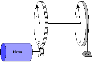
It is easy to figure out that if they are on the same shaft, the velocity (rotations per second) is the exact same. To calculate torque, you must use the moment arm balance equations from my statics tutorial. In this case, the radius is the moment arm.
radius_gear1 * torque_gear1 = radius_gear2 * torque_gear2
In this example, what minimum torque does the motor need to pull the weight up?
writing down the equations:
torque_motor * radius_gear1 = torque_gear2 * radius_gear2
torque_gear2 * radius_gear2 = torque_gear3 * radius_gear3
torque_gear3 * radius_gear3 = weight * radius_gear3
simplifying, we get:
torque_motor * radius_gear1 = weight * radius_gear3
so therefore the minimum required motor torque is
torque_motor = weight * radius_gear3 / radius_gear1
Now what if you wanted the weight to lift at 2 feet/sec. What rotations per second and direction must the motor rotate at?
writing down the equations:
rps_motor * radius_gear1 = rps_gear2 * radius_gear2
rps_gear2 = rps_gear3
rps_gear3 * 2*pi*radius_gear3 = velocity_weight
simplifying, we get:
rps_motor * radius_gear1 = rps_gear3 * radius_gear2
or
rps_motor * radius_gear1 = velocity_weight / (2*pi*radius_gear3) * radius_gear2
so therefore the required motor rps is
rps_motor = 2 ft/sec * radius_gear2 / (2*pi*radius_gear3 * radius_gear1)
Gear Pitch
When selecting your gears, the three most important numbers you must know are pitch, pitch diameter, and number of teeth.
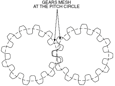
The pitch diameter is as shown. To calculate the pitch, simply use this equation:
Pitch = # teeth / pitch circle diameter (in inches)
For example, a gear with 72 teeth and a 1.5" pitch diameter is 48 Pitch. Gears that mesh must both have the same pitch and pressure angle (usually 20 degrees).
Gear Types
All gears, no matter the type, work on the same principles above. However the different types let you accomplish different things. Some types of gears have high efficiencies, or high gearing ratios, or work at different angles, for example. Below are the main common types. This is not a complete list. It is also possible to have a combination in types.
Note: The efficiencies listed are only typical. Because of many other factors could be present, the listed efficiencies should only be used as a guide. Often manufacturers will give you expected efficiencies in the datasheets for their gears. Remember, wear and lubrication will also dramatically affect gear efficiencies.
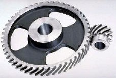
Spur Gears (~90% efficiency)
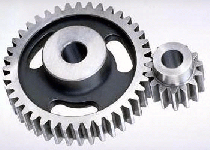
Spur gears are the most commonly used gears due to their simplicity and the fact that they have the highest possible efficiency of all gear types. Not recommend for very high loads as gear teeth can break more easily.
Helical Gears (~80% efficiency)
Helical gears operate just like spur gears, but offer smoother operation. You can also optionally operate them at an angle, too. Unfortunately, due to the complex shape, they are generally more expensive.
Sproket Gears With Chains (~80% efficiency)
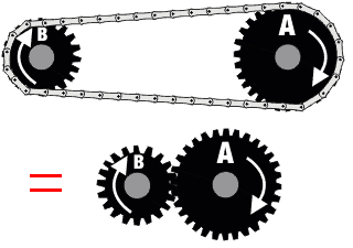
Two gears with a chain can be considered as three separate gears. Since there is an odd number, the rotation direction is the same. They operate basically like spur gears, but due to increased contact area there is increased friction (hence lower efficiency). Lubrication is highly recommended.
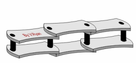
To change the length of any chain, you will need what is called a chain breaker. This is a cheap device you can buy at any bike store. It helps in removing and placing pins within the chain.
Bevel Gears (~70% efficiency)
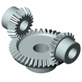
Bevel gears are good for changing the rotation angle. Unfortunately they suffer low efficiencies, so avoid use if possible.
Rack and Pinion (~90% efficiency)
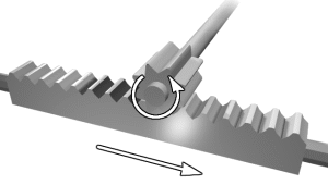
Rack and Pinion is the type of gearing found in steering systems. This gearing is great if you want to convert rotational motion into translational. Mathematically, use radius = 1 for the straight 'gear'.
Worm Gears (~70% efficiency)
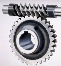
Worm gears have a very high gearing ratio. To mathematically calculate, consider the worm gear as a single tooth. Another advantage to the worm gear is that it is not back-drivable. What this means is only your motor can rotate the main gear, so things like gravity or counter forces will not cause any rotation. This is good say if you have a robot arm holding something heavy, and you don't want to waste power on holding torque. The efficiency is low, but lubrication really helps.
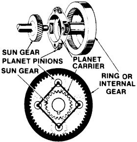
Planetary Gears (~80% efficiency)
Planetary gears have the highest commercially available gear ratios you would ever want to put on a robot. But since they are somewhat complicated, you would never need to build one, just use it. The datasheet should tell you the gearing ratio - I just wanted you to know if you need a really really high gearing ratio for a robot, planetary gears are the way to go. Even better, some planetary gears offer multiple gearing ratio's that are user configurable!